
Inductance
(1) Introduction
(2) Self Inductance
(3) Self induction of a long solenoid
(4) Energy in an inductor
(1) Introduction
- Before defining inductance first of all, we will define an inductor.
- Like capacitor, inductor is another component commonly in electronic circuits.
- An inductor consists of a coil wound on a core or former of a suitable material like solid or laminated iron. core or ferrites which are highly ferromagnetic substances.
- when a current through an inductor changes am emf is induced in it which opposes this change of current in the inductor.
- This property of inductor or coil due to which it opposes change of current through it called the inductance denoted by letter L.
- Unit of inductance is henry(H).
(2) Self Inductance
- Consider the figure given below
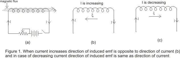
- When we establish a current through an inductor or coil, it generates a magnetic field and this result in a magnetic flux passing through the coil as shown in figure 1(a).
- If we vary the amount of current flowing in the coil with time, the magnetic flux associated with the coil also changes and an emf ξ is induced in the coil.
- According to the Lenz’s law, the direction of induced emf is such that it opposes its cause i.e. it opposes the change in current or magnetic flux.
- This phenomenon of production of opposing induced emf in inductor or coil itself due to time varying current in the coil is known as self induction.
- If I is the amount of current flowing in the coil at any instant then emf induced in the coil is directly proportional to the change in current i.e.
where L is a constant known as coefficient of self induction. - If (-dI/dt)=1 then ξ=L
Hence the coefficient of self induction of a inductor or coil is numerically equal to the emf induced in the coil when rate of change of current in the coil is unity. - Now from the faraday's and Lenz’s laws induced emf is
comparing equation 1 and 2 we have,
or Φ=LI - Again for I=1, Φ=L
hence the coefficient of self induction of coil is also numerically equal to the magnetic flux linked with the inductor carrying a current of one ampere - If the coil has N number of turn’s then total flux through the coil is
Φtot=NΦ
where Φ is the flux through single turn of the coil .So we have,
Φtot=LI
or L=NΦ/I
for a coil of N turns - In the figure given below consider the inductor to be the part of a circuit and current flowing in the inductor from left to right
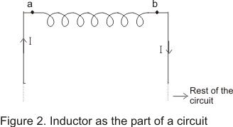
- Now when a inductor is used in a circuit, we can use Kirchhoff’s loop rule and this emf(Self induced emf) can be treated as if it is a potential drop with point A at higher potential and B at lower potential when current flows from a to b as shown in the figure
- We thus have
Vab=LdI/dt
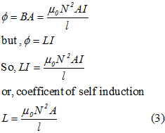
(3) Self induction of a long solenoid
- Consider a long solenoid of length l, area of cross-section A and having N closely wound turns.
- If I is the amount of current flowing through the solenoid them magnetic field B inside the solenoid is given by,

- Magnetic flux through each turn of the solenoid is,
(4) Energy in an inductor
- Changing current in an inductor gives rise to self induced emf which opposes changes in the current flowing through the inductor.
- This self inductance thus plays the role the inertia and it is electromagnetic analogue of mass in mechanics.
- So a certain amount of work is required to be done against this self induced emf for establishing the current in the circuit.
- In order to do so, the source supplying current in a circuit must maintain Potential difference between its terminals which is done by supplying energy to the inductor.
- Power supplied to the inductor is given by relation
P=ξI ---(4)
where
L is Self inductance and
dI/dt is rate of change of current I in the circuit. - Energy dW supplied in time dt would be
dW=Pdt
=LI(dI/dt) dt
=LIdI
and total energy supplied while current I increases from o to a final value I is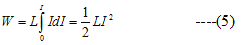
- Once the current reaches its final value and becomes steady ,the power input becomes zero.
- The energy so far supplied to the inductor is stored in it as a form of potential energy as long as current is maintained.
- When current in circuit becomes zero, the energy is returned to the circuit which supplies it.
Hi,
ReplyDeleteI want you to notice that you are regularly copying material from our website http://physicscatalyst.com without even linking back to our website. i do not want our material to be copied in such a way. You can obviously give our links if it help you but not all our material. To avoid action please remove our material from your blog(s) and you can give our links to your users if you want.
hope you get what i am trying to say.
physicscatalyst